


It is often taught that to diagnose a restrictive air filter is as simple as a visual inspection to see if it’s plugged. Then, if the filter is dirty, replace it. Once this obvious defect is fixed, everything is assumed to work correctly. Could there be more to it? What if the new air filter you installed is perfectly clean and still causing airflow issues? How would you test, diagnose, and solve this problem?
Measuring the pressure drop over an air filter reveals valuable clues to its influence on a system. This simple test helps you determine if the filter is adequate for the application it’s being used in.
Filter pressure drop testing enables you to include the type of filter, its surface area, and the filter rack opening as variables that are rarely considered. Let’s look at how to test, diagnose, and correct a restrictive air filter.
Measuring Air Filter Pressure Drop
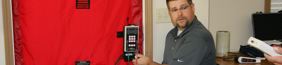
To measure air filter pressure drop you’ll need a quality static pressure kit to obtain pressure measurements before and after the filter. A good static pressure kit should have the following test instrument and accessories in it:
- Manometer (analog or digital)
- Test hoses (3/16” i.d.)
- Static pressure tips
- 3/8” drill bit with protective sheath
- 3/8” test plugs.
Pressure testing always begins with a visual inspection of the equipment and installation to head off any potential issues. Be sure you look before you drill — you don’t want to drill into a drain pan or refrigeration tubing.
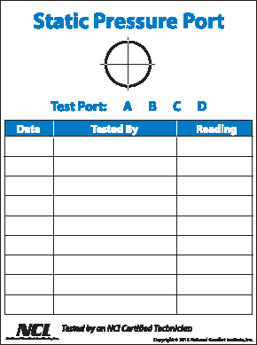
These Static Pressure Testing Port stickers can be used when testing to see if air filters are restricting air flow. They can be ordered through the NCI Store. Go to bit.ly/StaticPSIstickers.
Once your inspection is complete you can begin testing. To measure filter pressure drop, follow these five simple steps:
- Install a test port into the duct or equipment on the entering air side of the filter by drilling a 3/8” test hole. This will be your pressure measurement before air enters the filter.
- Install another test port into the duct or equipment on the leaving air side of the filter by drilling another 3/8” test hole. This will be your pressure measurement after air leaves the filter.
- Setup your manometer where you can easily see the display as you measure pressure. Attach a test hose to each pressure tap on the manometer and insert a static pressure tip into the opposite end of each of these hoses.
- Insert the static pressure tips into the 3/8” test ports you drilled on each side of the air filter. Be sure to face the static pressure tips into the airflow.
- The live pressure drop over the filter will now appear on the display of your manometer. Record the reading to diagnose filter pressure drop. Place test plugs in your test ports when finished.
Diagnosing Air Filter Pressure Drop Readings
Once you’ve obtained your filter pressure drop readings, you’ll need to determine if those readings are acceptable. To see if the filter is too restrictive, you can use a rule of thumb NCI teaches based on the fan’s rated static pressure.
Ideally, filter pressure drop should not exceed 20% of the fan’s rated maximum static pressure. You can find this fan rating on the air handling equipment’s data plate often located on the door or inside the cabinet.
Let’s say you’re testing filter pressure drop on a gas furnace that’s maximum rated static pressure is .50 inches of water column. Multiply the maximum rated static pressure of the fan by 20% or .20 to come up with the ideal filter pressure drop. In this example the filter pressure drop should not exceed .10 inches of water column (.20 x 50% = .10 inches of water column).
If filter pressure drop exceeds 20% of the fans rated pressure, you’ll probably need to make some changes in the system in order for it to work properly. If filter pressure drop is extremely low, look for signs of filter bypass or a poorly constructed filter rack assembly.
Correcting Excessive Air Filter Pressure Drop Issues
Once you start measuring filter pressure drop, the odds are pretty high you’ll uncover a filter issue in the first three HVAC systems you test. Time to look at options that can reduce the pressure drop across the filter.
The easiest option is to remove the existing restrictive filter and replace it with one that has a lower pressure drop, such as fiberglass. This can immediately solve the problem and drastically improve system performance and comfort. Be sure to measure the new filter pressure drop after the old filter has been replaced to ensure it worked as intended.
There will be instances that the solution isn’t this simple and you’ll need to increase filter surface area to reduce the pressure drop. The most common ways to do this include:
- Installing a custom filter rack
- Installing filters in a “V” shaped pattern
- Adding a return drop with an additional air filter
- Adding multiple return air filter grilles.
These options will often solve the problems associated with high filter pressure drop. When you double the filter surface area in a system, the pressure drop over the filters will typically reduce by more than 50%. You’ll need to resize the filter when employing these options as well. This can be calculated in three steps.
Resizing the Air Filter
To resize an air filter you’ll need to know the recommended air velocity through it. This measurement is specified in feet per minute or FPM. The manufacturer’s specifications are the source of this information, but can be difficult to find. When unavailable, use these typical filter velocities that have proven to work well in the field based on actual testing.
| Fiberglass | 400-500 | Electronic | 350-450 |
| Hog Hair | 350-400 | Washable | 350-450 |
| 40% Pleated | 300-350 | Electrostatic | 200-300 |
| 90% Media | 150-200 | HEPA | 200-250 |
Step One: Calculate the square feet of filter area needed for the HVAC system using the following formula:
Required Equipment Airflow (CFM) ÷ Filter Velocity
= Square Feet of Filter Needed
If the system you were resizing the air filter on is 3.5 ton, take the required airflow (in this example we’ll use 400 CFM per ton) and divide by the velocity you need across the air filter. In this example we’ll aim to maintain a filter velocity of 400 fpm at 1,400 cfm. To figure square feet of filter area the formula would appear as follows:
1400 CFM ÷ 400 FPM
= 3.5 Sq. Ft. of filter area needed.
To achieve 400 fpm filter velocity at a fan airflow rate of 1,400 cfm, there needs to be 3.5 square feet of filter area. Next, the size of the filter/filters will need to be calculated.
Step Two: Calculate the size of the filter/filters in square feet using the following formula:
Length x Width ÷ 144
= Square Feet of each filter
Let’s say you only have enough room to install an air filter that is 14” X 20” in size. You need to figure out the size of the 14” x 20” filters in square feet. Plug in the filter dimensions into the formula and do the math.
14” x 20” = 280 sq. in. ÷ 144 sq. in. = 1.94 sq. ft.
Now you have the size in square feet of the filter you’ll be using. Next, this size will need to be compared against the required amount of square feet that was determined back in step one to determine how many filters of this size will be needed.
Step Three: Calculate the number of filters needed using the following formula:
Sq. Ft. of filter required ÷ Sq. Ft. of each filter used
= Number of filters
From the information found in steps one and two you can complete the formula in the example.
3.5 Sq. Ft. of filter needed ÷ 1.94 sq. ft. each
= 1.8 filters needed
You’ll have to round up to 2 – 14” x 20” filters for this 3.5 ton system. Since 2 filters are needed to obtain adequate filter surface area, they would need to be installed in a V-type installation or multiple filter grilles.
Air Filter Repair Verification
After a filter modification has been completed, verify the pressure drop of the new filter(s) at the designed velocity and airflow. Remember, engineering is only an estimate of what should happen under live operating conditions. Test and verify to ensure your work actually does what you intended. Anything else is a guess.
Some systems won’t be repaired easily; this is a reality of working in the field. Don’t let it discourage you from offering what your customers need and want.
 David Richardson serves the HVAC industry as a curriculum developer and trainer at the National Comfort Institute (NCI). NCI specializes in training focused on improving, measuring, and verifying HVAC and Building Performance. If you’re an HVAC contractor or technician interested in learning how static pressure testing can help your company, contact David at davidr@ncihvac.com or call him at 800-633-7058.You can learn more at NCI’s website, www.nationalcomfortinstitute.com.
Leave a Reply
You must be logged in to post a comment.